International shipping Secure payment
No products
Prices are tax included
Product successfully added to your shopping cart
There are 0 items in your cart. There is 1 item in your cart.
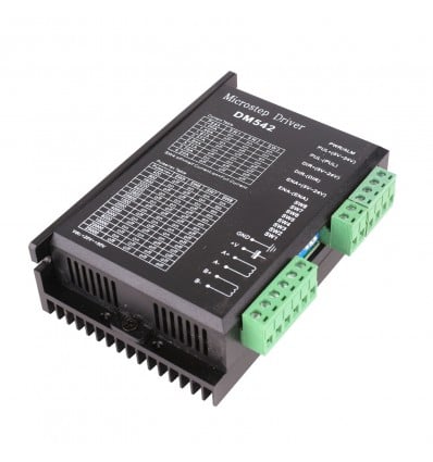
DM542 Stepper Motor Driver (4.2A)
9MDTM542
New
The DM542 Stepper Motor Driver offers high torque at all speeds – Ideal for CNC, 3D printing and machines requiring precise numerical value control.
5+ In Stock Items
Free shipping on orders over R1250 - courier delivery and within South Africa
The DM542 is one of the best value-for-money hybrid stepping motor drivers on the market, and is designed to drive bipolar hybrid stepper motors with outside diameters of between 42mm and 86mm at less than 4.0A phase current. By utilizing a similar circuit to typical servo control methods, the DM542 runs smoothly at both high and low speeds – with little to no noise or vibration.
Some of the top features of this stepping motor driver, when compared to more affordable alternatives like the TB6560, is that it maintains a high torque regardless of the speed at which it’s running. Additionally, this enhances the positional accuracy as well, making it ideal for professional applications within machines such as 3D printers, CNC milling machines and other machines with numerical control devices.
The DM542 also offers a semi-flow function, which automatically reduces the current down to 70% of the output current. This activates when the driver receives no pulse signals for 500ms, and essentially acts as a “semi-sleep” mode, to reduce power usage and prevent possible overheating between uses. To further prevent overheating or heat related problems, be sure to install this stepping motor driver away from other heating devices, and allow for 20mm of open space surrounding the unit for effective heat dispersion.
|
Electrical Specifications: |
|
|
Input voltage |
– 18VDC to 50VDC |
|
Input current |
– Less than 4.0A |
|
Output current |
– 1.0A~4.2A Peak (3.00A RMS) |
|
Consumption |
– Consumption : 80W ; Internal Limit : 6A |
|
Working Temperature |
– -10~45℃ |
|
Storage Temperature |
– -40℃~70℃ |
|
Humidity |
– No condensation, no water droplets. <90% RH |
|
Gas |
– Prohibition of combustible gases and conductive dust |
|
Weight |
– 300g |
|
Features and Technical Specifications: |
|
|
Average Current Control |
– 2-Phase Sinusoidal Output Current Drive |
|
Input/Output Method |
– Opto-isolated Signal |
|
Command Input Terminal |
– Offline |
|
Phase Current Setting Output Channels |
– 8 |
|
Subdivision Channels |
– 15 |
|
Motor Torque Control |
– Relative to Speed ; Not Relative to Steps/Revolutions |
|
Short Circuit Protection |
– Overvoltage; Under-voltage; Overcurrent; Phase |
|
Additional Features |
– High Starting Torque and Speed |
|
|
– High Holding Torque at All Speeds |
|
|
– Automatic Idle-Current Reduction |
|
|
– Exceptional Performance/Low Price |
Connector Pin Assignments and Descriptions
|
Pin Function |
Details |
|
|
|
|
PUL +,PUL- |
Pulse signal: PUL+ is the positive end of pulses input pin PUL- is the negative end of pulse input pin |
|
DIR+,DIR- |
DIR signal: DIR+ is the positive end of direction input pin DIR- is the negative end of direction input pin |
|
ENBL+ |
Enable signal: ENBL+ is the positive end of direction input pin. This signal is used for enabling/disabling the driver. High level for enabling the driver and low level for disabling the driver. |
|
ENBL- |
ENBL- is the negative end of direction input pin. Often left unconnected (Enabled) |
DIP Pin Functions and Function Choices
The DM542 Stepper Motor Driver utilizes the SW1 to SW8 DIP pins to control the function of the stepper motors, the output current, as well as whether the current must be on standstill or not. The first three (SW1, SW2 and SW3) pins define the output current settings and should be adjusted according to the dynamic current necessary for your motor. The next pin (SW4) determines the current standstill setting, and is essentially a soft on/off switch, which sets the current to half when the motor is not in use. The final four pins (SW 5, SW6, SW7 and SW8) are for setting the micro step resolution, defining the amount of pulses per revolution.
DIP Pins SW4 to SW8: Micro Step Revolution Settings Chart
|
SW5 |
OFF |
ON |
OFF |
ON |
OFF |
ON |
OFF |
ON |
OFF |
ON |
OFF |
ON |
OFF |
ON |
OFF |
|
SW6 |
ON |
OFF |
OFF |
ON |
ON |
OFF |
OFF |
ON |
ON |
OFF |
OFF |
ON |
ON |
OFF |
OFF |
|
SW7 |
ON |
ON |
ON |
OFF |
OFF |
OFF |
OFF |
ON |
ON |
ON |
ON |
OFF |
OFF |
OFF |
OFF |
|
SW8 |
ON |
ON |
ON |
ON |
ON |
ON |
ON |
OFF |
OFF |
OFF |
OFF |
OFF |
OFF |
OFF |
OFF |
|
PULSE/REV |
400 |
800 |
1600 |
3200 |
6400 |
12800 |
25600 |
1000 |
2000 |
4000 |
5000 |
8000 |
10000 |
20000 |
25000 |
DIP Pins SW1 to SW3: Output Current Settings
When deciding on these settings, be sure to check your stepper motors and set the output current to a value that best caters to your motors’ input current requirement.
|
Output Current (A) |
||||
|
SW1 |
SW2 |
SW3 |
PEAK |
RMS |
|
ON |
ON |
ON |
1.00 |
0.71 |
|
OFF |
ON |
ON |
1.46 |
1.04 |
|
ON |
OFF |
ON |
1.91 |
1.36 |
|
OFF |
OFF |
ON |
2.37 |
1.69 |
|
ON |
ON |
OFF |
2.84 |
2.03 |
|
OFF |
ON |
OFF |
3.31 |
2.36 |
|
ON |
OFF |
OFF |
3.76 |
2.69 |
|
OFF |
OFF |
OFF |
4.20 |
3.00 |
Troubleshooting Chart
If you are experiencing problems relating to the DM542 Stepper Motor Driver, utilize the following chart, which notes some of the most common problems, as well as reasons for the problems and possible solutions.
|
Problem / Alarm |
Potential Reasons |
Possible Solution |
|
|
|
|
|
LED off turn |
Wrong connection for power |
Check wiring of power |
|
Low-voltages for power |
Increase voltage of power |
|
|
Motor doesn’t run, without holding torque |
Wrong connection of stepper motor |
Correct its wiring |
|
RESET signal is effective when offline |
Make RESET ineffective |
|
|
Motor doesn’t run, but maintains holding torque |
Low or absent input pulse signal |
Adjust PMW & signal level |
|
Motor runs wrong direction |
Wrong wires’ connection |
Change connection for any 2 wires |
|
Wrong input direction signal |
Change direction setting |
|
|
Motor’s holding torque is low or ineffective |
Too small relative to current setting |
Correct rated current setting |
|
Acceleration is too fast |
Reduce the acceleration |
|
|
Motor stalls |
Check for mechanical failure |
|
|
Driver does not match with the motor |
Change to a more suitable driver |
No customer reviews for the moment.


